Dans cette partie nous allons voir comment lire une entrée analogique. Nous allons tester cela à l’aide des projets suivants : - un potentiomètre dont nous allons afficher sur port série ; - une photorésistance dont nous allons afficher la valeur sur le port série ; Et dans la partie un peu plus, nous allons mélanger ces programmes et les ajouter des anciens. - deux photorésistances et un potentiomètre et nous allons afficher la valeur sur le port série. - un potentiomètre et nous allons faire varier la lumière d’une LED en fonction de la valeur du potentiomètre.
Un potentiomètre sur port série
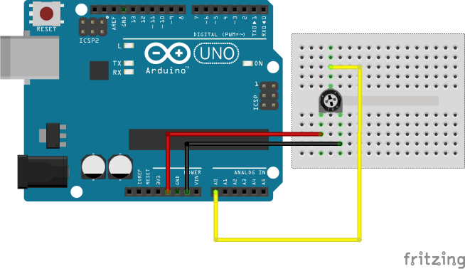
Voici le schéma de ce projet :

Voici le code de ce projet :
------------------------------------------------------------------------------
--                                                                          --
--                                                                          --
--                         A n a l o g   E n t r y                          --
--                                                                          --
--                                M a i n                                   --
--                                                                          --
--    Copyright (C) 2017 Bardot Sébastien                                   --
--    More information on http://lvcetada.e-monsite.com/ or by mail on      --
--    lvcetada@gmail.com                                                    --
--                                                                          --
--    This program is free software: you can redistribute it and/or modify  --
--    it under the terms of the GNU General Public License as published by  --
--    the Free Software Foundation, either version 3 of the License, or     --
--    (at your option) any later version.                                   --
--                                                                          --
--    This program is distributed in the hope that it will be useful,       --
--    but WITHOUT ANY WARRANTY; without even the implied warranty of        --
--    MERCHANTABILITY or FITNESS FOR A PARTICULAR PURPOSE.  See the         --
--    GNU General Public License for more details.                          --
--                                                                          --
--    You should have received a copy of the GNU General Public License     --
--    along with this program.  If not, see <http://www.gnu.org/licenses/>. --
--                                                                          --
--                                                                          --
--    This package and its children are based on AVR-Ada Library.           --
--                                                                          --
--                                                                          --
------------------------------------------------------------------------------

with AVR;
with AVR.MCU;
with AVR.Real_Time.Delays;
with AVR.UART;

use AVR;
use AVR.MCU;

procedure AnalogEntry is
begin
   -- Set the prescaler to 128 for a maximum resolution
   -- and activate the CAN
   ADCSRA_Bits := (ADEN_Bit => True,
                   ADPS0_Bit => True,
                   ADPS1_Bit => True,
                   ADPS2_Bit => True,
                   others => False);

   -- Set the Reference voltage to AVCC with external capacitor at AREF pin
   ADMUX_Bits := (REFS0_Bit => True,
                  others => False);

   -- Initialise the serial port
   AVR.UART.Init (103);

   loop
      -- Set the ADSC_Bit to true to initialise the conversion
      ADCSRA_Bits(ADSC_Bit) := True;
      -- Wait the conversion
      while(ADCSRA_Bits(ADSC_Bit)) loop
         null;
      end loop;
      -- Print the result and return to a new line
      AVR.UART.Put(ADC);
      AVR.UART.CRLF;
      delay 0.1;
   end loop;
end AnalogEntry;
Les fichiers de ce programme peuvent être téléchargés ici.
Voici le code avec la librairie GPIO dans laquelle la fonction « AnalogRead » a été ajoutée, elle prend en paramètre le numéro du port analogique (A0-A7) et renvoie la valeur lue (elle renvoie 0 ou 1024 sur les ports digitaux suivant leurs états, bas = 0 et haut = 1024).
------------------------------------------------------------------------------
--                                                                          --
--                                                                          --
--                         A n a l o g   E n t r y                          --
--                                                                          --
--                                M a i n                                   --
--                                                                          --
--    Copyright (C) 2017 Bardot Sébastien                                   --
--    More information on http://lvcetada.e-monsite.com/ or by mail on      --
--    lvcetada@gmail.com                                                    --
--                                                                          --
--    This program is free software: you can redistribute it and/or modify  --
--    it under the terms of the GNU General Public License as published by  --
--    the Free Software Foundation, either version 3 of the License, or     --
--    (at your option) any later version.                                   --
--                                                                          --
--    This program is distributed in the hope that it will be useful,       --
--    but WITHOUT ANY WARRANTY; without even the implied warranty of        --
--    MERCHANTABILITY or FITNESS FOR A PARTICULAR PURPOSE.  See the         --
--    GNU General Public License for more details.                          --
--                                                                          --
--    You should have received a copy of the GNU General Public License     --
--    along with this program.  If not, see <http://www.gnu.org/licenses/>. --
--                                                                          --
--                                                                          --
--    This package and its children are based on AVR-Ada Library.           --
--                                                                          --
--                                                                          --
------------------------------------------------------------------------------

with AVR;
with AVR.Real_Time.Delays;
with AVR.UART;
with GPIO;

use AVR;
use GPIO;

procedure AnalogEntry is
begin
   -- Initialise the serial port
   AVR.UART.Init (103);

   loop
      AVR.UART.Put(AnalogRead(A0));
      AVR.UART.CRLF;
      delay 0.1;
   end loop;
end AnalogEntry;
Les fichiers de ce programme peuvent être téléchargés ici.
Les valeurs obtenues par une photorésistance
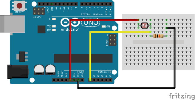
Une photorésistance est une résistance dans la valeur varie en fonction de la luminosité ambiante. Nous allons donc lire la valeur de la photorésistance et l’afficher sur le port série. Voici le schéma de ce projet :

Pour le code, c’est le même que la partie précédente. J’aurais pu changer le numéro de port, mais nous allons faire cela dans la partie suivante.
Un peu plus
Trois entrées analogiques
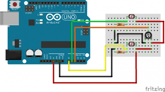
Ce projet va être un mélange des deux précédents. Pourquoi me diriez-vous ? Tout simplement, parce que trop souvent on ne voit que des cas isolés alors que parfois des subtilités empêchent de les réunir. Je le ferai souvent, même si ici ça ne pose pas de problème ici. Donc ce projet va prendre en entrée deux photorésistances qui ont des valeurs différentes ainsi qu’un potentiomètre.
Voici le schéma de ce projet :

Voici le code de ce projet avec la librairie GPIO :
------------------------------------------------------------------------------
--                                                                          --
--                                                                          --
--                         A n a l o g   E n t r y                          --
--                                                                          --
--                                M a i n                                   --
--                                                                          --
--    Copyright (C) 2017 Bardot Sébastien                                   --
--    More information on http://lvcetada.e-monsite.com/ or by mail on      --
--    lvcetada@gmail.com                                                    --
--                                                                          --
--    This program is free software: you can redistribute it and/or modify  --
--    it under the terms of the GNU General Public License as published by  --
--    the Free Software Foundation, either version 3 of the License, or     --
--    (at your option) any later version.                                   --
--                                                                          --
--    This program is distributed in the hope that it will be useful,       --
--    but WITHOUT ANY WARRANTY; without even the implied warranty of        --
--    MERCHANTABILITY or FITNESS FOR A PARTICULAR PURPOSE.  See the         --
--    GNU General Public License for more details.                          --
--                                                                          --
--    You should have received a copy of the GNU General Public License     --
--    along with this program.  If not, see <http://www.gnu.org/licenses/>. --
--                                                                          --
--                                                                          --
--    This package and its children are based on AVR-Ada Library.           --
--                                                                          --
--                                                                          --
------------------------------------------------------------------------------

with AVR;
with AVR.Real_Time.Delays;
with AVR.UART;
with GPIO;

use AVR;
use GPIO;

procedure AnalogEntry is
begin
   -- Initialise the serial port
   AVR.UART.Init (103);
   AVR.UART.Put("Phr 1   |  Phr 2   |  Pot 1");

   loop
      AVR.UART.Put(AnalogRead(A0));AVR.UART.Put("   |  "); -- Photoresistance 1
      AVR.UART.Put(AnalogRead(A1));AVR.UART.Put("   |  "); -- Photoresistance 2
      AVR.UART.Put(AnalogRead(A2));                        -- Portentiometer 1
      AVR.UART.CRLF;
      delay 0.1;
   end loop;
end AnalogEntry;
Les fichiers de ce programme peuvent être téléchargés ici.
Un potentiomètre qui contrôle deux LED
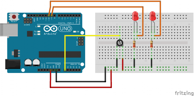
Pour ce projet, nous allons utiliser un potentiomètre pour faire varier la luminescence de deux LED. Nous allons lire la valeur du potentiomètre sur une entrée analogique. Cette valeur sera utilisée pour faire varier la luminosité des LED. Nous allons utiliser ce qui à été vu dans la partie "Un peu plus" pour modifier la valeur d'une LED. En effet, ainsi nous n’aurons pas de conversion de valeur (bien qu’un diviser par 4 n’est pas compliqué à écrire) et ça fera une piqûre de rappel. La D9 brillera dans le même sens que le potentiomètre et la D10 en sens inverse.
Voici le schéma de ce projet :

Voici le code de ce projet :
------------------------------------------------------------------------------
--                                                                          --
--                                                                          --
--                         A n a l o g   E n t r y                          --
--                                                                          --
--                                M a i n                                   --
--                                                                          --
--    Copyright (C) 2017 Bardot Sébastien                                   --
--    More information on http://lvcetada.e-monsite.com/ or by mail on      --
--    lvcetada@gmail.com                                                    --
--                                                                          --
--    This program is free software: you can redistribute it and/or modify  --
--    it under the terms of the GNU General Public License as published by  --
--    the Free Software Foundation, either version 3 of the License, or     --
--    (at your option) any later version.                                   --
--                                                                          --
--    This program is distributed in the hope that it will be useful,       --
--    but WITHOUT ANY WARRANTY; without even the implied warranty of        --
--    MERCHANTABILITY or FITNESS FOR A PARTICULAR PURPOSE.  See the         --
--    GNU General Public License for more details.                          --
--                                                                          --
--    You should have received a copy of the GNU General Public License     --
--    along with this program.  If not, see <http://www.gnu.org/licenses/>. --
--                                                                          --
--                                                                          --
--    This package and its children are based on AVR-Ada Library.           --
--                                                                          --
--                                                                          --
------------------------------------------------------------------------------

with AVR;
with AVR.MCU;
with AVR.Real_Time.Delays;
with GPIO;
with Interfaces;

use AVR;
use GPIO;
use Interfaces;

procedure AnalogEntry is
   temp : Unsigned_16 := 0;
begin
   -- D9 and D10 in AnalogOutput mode
   PinMode(D9, AnalogOutput);
   PinMode(D10, AnalogOutput);
   -- Change timer to be on 10 bit, so 0-1023 and no conversion for the
   -- analog enter
   MCU.TCCR1A_Bits(MCU.WGM11_Bit) := True;
   MCU.TCCR1A_Bits(MCU.WGM12_Bit) := True;
   -- Write value temp on D9 and D10
   AnalogWrite(D9, temp);
   AnalogWrite(D10, 1023 - temp);
   loop
      -- Read the value on Analog pin A0
      temp := AnalogRead(A0);
      -- Write the value on D9 and D10
      AnalogWrite(D9, temp);
      AnalogWrite(D10, 1023 - temp);
      delay 0.1;
   end loop;
end AnalogEntry;
Les fichiers de ce programme peuvent être téléchargés ici.


Ajouter un commentaire